PSA: Mistake in installation guide can damage PS1Digitals

Markovich2001

New member
My PS1Digital is damaged due to a mistake in the installation guide (it's incorrect in the installation video as well). Some colors, particularly the G3 G4 and G5 signals drop out or get corrupt a lot of the time and show X'es on the signal test. Everything worked fine for roughly 40-60 hours of gameplay on the PS1 until this problem started happening and presented itself. I have already contacted Black Dog directly with this issue and asked for help about it (update: I have been offered an exchange, thank you for understanding!). There was no place to put pictures in the submission so I posted here as well. Here are the details on the problem.

The guide tells you to "Remove the pressed dimple with side cutters" as pictured:
chrome_S82jpSD0V7.png

This is the dimple I removed as you can clearly see in the following picture. Note that you can tell this is the incorrect dimple (the heat pad sticking to the top shield makes this obvious), but it is not obvious at time of installation if you're following the guide:
biggurippy.jpg

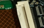
Closeup of the damage:
View attachment 72
 

Attachments

Last edited:

invaderyoyo

New member
My connector and ribbon cable were damaged as well. I didn't double check the guide so I just assumed I had cut the wrong dimple and went ahead and cut the other one. So far it's been working fine, but I didn't realize it could cause problems down the line. Here's a picture. You can see that a chunk of the connector came off. The ribbon cable is visibly bent at that spot. I'll see if I can get a close up.


citrus3000psi

Administrator
Staff member
The dimple cut was added at the last minuet as it seems not all cases have this issue some are deeper than others.

I have since fixed the install docs (totally my fault) If there are any issues I will not hesitate to fix anyone's boards if they need it.
 

invaderyoyo

New member
The dimple cut was added at the last minuet as it seems not all cases have this issue some are deeper than others.

I have since fixed the install docs (totally my fault) If there are any issues I will not hesitate to fix anyone's boards if they need it.
This is what the cable looks like. Do you think it might fail in the future? Gotta be honest, I’m not looking forward to installing that flex cable again.


Timmy_Gman

New member
Wow I'm glad I stumbled upon this, I installed mine last night and for the life of me couldn't figure out why the rf shield was slightly bulging. Causing the disc open switch to not be triggered for my xstation. I'm glad I didn't fully screw it down and I would of for sure smashed the ribbon connector. Thatnks for the post saved me a ton!!
 

pevkoss

New member
Wow, this happened to me as well. I was blaming myself at first for the mistake but then realized, after careful examination, that the incorrect dimple was listed in the guide. Luckily, only the flex connector flap lock was slightly damaged. The flex cable is not damaged. My PS1Digital works w/o issue after some long play sessions. Glad that the guide was updated so that others are spared the pain. (images below)

flap-lock-damage1.jpgflap-lock-damage2.jpgflap-lock-damage3.jpgflex-cable-no-damage1.jpgflex-cable-no-damage.2.jpg

@Markovich2001 Thanks for reporting it.
@citrus3000psi Thanks for updating the guide for others.
 

dryja123

New member
Dang, I just noticed this too. I was hoping to never have to open the PSX again, but I just looked at a photo I took when I installed my X-Station and there's damage on the connector.
 

Duo_R

New member
Should we just say cut both dimples? I noticed the video and the guide show different holes (and I commented on the video). Which is correct one?
 

CZroe

New member
Just found where I noted a couple more errors last year:

The guide says to check for shorts on the test point before it tells you to connect the flex cables. Obviously, this will only tell you if the PS1Digital is internally shorted and will not reveal any bridges from your soldering.

The guide indicates the wrong point for the PSNee DAT connection at IC706 on PU-20 boards. Pin 1 is hard to see but the arrow is pointing to Pin 2. It should be pointing to Pin 1.

Sorry I didn’t say anything earlier but I changed phones and lost my notes.
 
Top